PFC Configuration for Congestion on Device
This section outlines the steps for configuring Priority Flow Control (PFC) and verifying its functionality when congestion occurs on the device (Device1). The setup uses VLAN 100 traffic with CoS priority 0 and ensures proper flow control by applying a shaper on the egress interface of Device1.
Topology
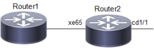
The topology consist of a client that act as Traffic Generator (TG) to send traffic to Device 1 on interface xe65 Device1.
Figure 57. PFC for Traffic Congestion on Device
Configuration
Use this procedure is to apply PFC when congestion occurs on Device1.
| 1. | Enable Data Center Bridging (DCB) and Priority-based Flow Control (PFC) on the bridge on Device 1. |
!
bridge 1 protocol ieee vlan-bridge
!
vlan database
 vlan-reservation 4001-4094
!
 vlan 100 bridge 1 state enable
priority-flow-control enable bridge 1
| 2. | Configure queue 0 as lossless with priority enabled in the default queuing policy. |
!
policy-map type queuing default default-out-policy
 class type queuing default q0
  priority
  lossless
  exit
!
!
interface cd1/1
 shape rate 100 mbps burst 1000
!
| 3. | Configure egress port cd1/1 and ingress xe65 Interfaces. Following sample commands, configures interface cd1/1 with rate shaping at 100 Mbps and MTU as 9216 for jumbo frames and interface xe65 with PFC priority as 0. |
!
interface cd1/1
 description connected to Router1
 switchport
 bridge-group 1
 switchport mode trunk
 switchport trunk allowed vlan all
 load-interval 30
 mtu 9216
 shape rate 100 mbps burst 1000
!
!
interface xe65
 description connected spirent
 switchport
 bridge-group 1
 switchport mode trunk
 switchport trunk allowed vlan all
 priority-flow-control mode on
 priority-flow-control enable priority 0
 load-interval 30
 mtu 9216
!| 4. | Configure the Traffic Generator (TG) to send traffic to VLAN-tagged traffic on VLAN 100. Set Class of Service (CoS) to 0. Ensure the TG is connected to interface xe65 on Device1. Send bidirectional traffic or add a static MAC entry via CLI to ensure unicast forwarding. |
| 5. | Send traffic at a rate exceeding the 100 Mbps shaping rate on interface cd1/1 to create congestion, causing queue 0 to fill up and trigger PFC for priority 0. |
Validations
Execute the following command on Device1 to check PFC statistics:
#show priority-flow-control statistics bridge  1
bridge : 1
interface pri pause sent     pause received
===========================================
xe65      0  7819702        0
xe65      1  0              0
xe65      2  0              0
xe65      3  0              0
xe65      40          0
xe65      5  0              0
xe65      6  0              0
xe65      7  0              0
Here is the explanation of the "show command" output fields.
|
Fields |
Description |
|---|---|
|
Pause Sent (7819702): |
Indicates that the Device 1 has generated PFC frames for priority 0 to notify the peer device to pause traffic. |
|
Pause Received (0): |
Indicates that no PFC frames were received from the peer device. |
#show interface counters rate mbps
+-------------------+--------------+-------------+--------------+-------------+
|     Interface     |    Rx mbps   |    Rx pps   |    Tx mbps   |    Tx pps   |
+-------------------+--------------+-------------+--------------+-------------+
   cd1/1                0.00           1             100.01         97668
   xe65                 100.01         97669         1.04           2037