DCBX Configuration for PFC via LLDP
Configuring PFC parameter exchange typically involves enabling PFC mode, LLDP, activating DCBX, turning on PFC, and allowing the negotiation of control for each traffic priority (priorities 0–7).
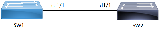
Topology
The topology involves two switches SW1 and SW2 directly connected and enabled with DCBx and PFC.
Figure 55. PFC Configuration
Configuration
The following procedure configures PFC parameters and sent them in LLDP messages.
| 1. | Create bridge and enable DCB and PFC on SW1 and SW2. |
Copy
bridge 1 protocol ieee vlan-bridge
data-center-bridging enable bridge
priority-flow-control enable bridge1| 2. | Set interface cd1/1 on SW1 and SW2 to layer 2 and bind it to bridge group. |
Copy
interface cd1/1
 switchport
bridge-group 1| 3. | Enable LLDP and DCBx on SW1 and SW2. Set LLDP for transmit and receive mode on the interface. Set the TLVs enabled for transmission on the interface to send an IEEE 802.1 organizationally specific TLV set in the packet. |
Copy
!
lldp-agent
 set lldp enable txrx
 lldp tlv ieee-8021-org-specific data-center-bridging select
 dcbx enable
!| 4. | Configure PFC on SW1 and SW2. Set the maximum number of priorities allowed for priority flow control on the interface. Enable PFC on priorities 0,1, and 2 |
Copy
!
priority-flow-control mode auto
priority-flow-control cap 3
priority-flow-control link-delay-allowance 65345
priority-flow-control enable priority 0 1 2
!
on SW2.
Copy
!
priority-flow-control mode auto
priority-flow-control cap 6
priority-flow-control link-delay-allowance 5678
priority-flow-control enable priority 5 6 7
!