BGP Four Bytes ASN with VPLS Configuration
Overview
In case of BGP-VPLS with four bytes ASN, RD will have administrator field expanded to accommodate 4 byte ASN whereas assigned number field remains two bytes. This adjustment allows the RD to continue providing unique identification for VPLS instances.
Enabling or disabling the four bytes ASN capability (bgp extended-asn-cap) requires the removal of certain existing configurations, such as VRFs associated with L3VPN and , as well as BGP auto-discovery configuration used in LDP-VPLS.
Prerequisites
Ensure that the loopback and core interfaces are configured with IPv4 addresses.
Copy
interface lo
 ip address 127.0.0.1/8
 ip address 30.0.1.2/32 secondary
 ipv6 address ::1/128

interface xe4
ip address 10.0.1.12/31
OSPF Configuration
Configure OSPF with router ID and advertise the networks. Set the interface as an OSPF point-to-point network type.
Either ISIS or OSPF can be used as an IGP protocol.
Copy
router ospf 100
 ospf router-id 30.0.1.2
network 10.0.1.12/31 area 0.0.0.0
network 30.0.1.2/32 area 0.0.0.0

interface xe4
ip ospf network point-to-point
Enable RSVP globally using the router rsvp command, and configure the interface with label-switching and RSVP support using label-switching and enable-rsvp commands.
Either RSVP or LDP can be used for transport.
Copy
router rsvp

Interface xe4
label-switching
enable-rsvp
Topology
The topology shows an MPLS Layer 2 VPN setup where CE1 and CE2 connect via PE1 and PE2, both in AS 80000. Core router P1 performs label switching, with /31 point-to-point links and /32 loopbacks used for routing and MPLS label distribution.
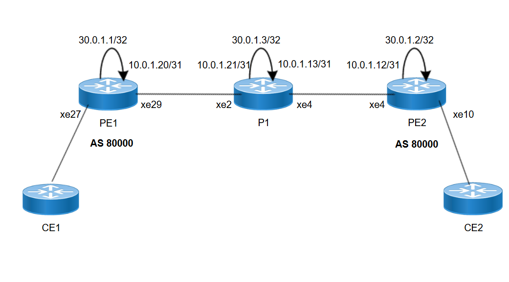
Figure 54. BGP 4-bytes ASN with VPLS
Configuration
This configuration sets up MPLS Layer 2 VPN using RSVP and OSPF for IGP routing. BGP is configured for VPLS signaling and interfaces are prepared for MPLS label switching and customer VLAN access. The setup enables end-to-end connectivity between CE1 and CE2 over VPLS service using BGP 4 byte ASN.
|
1.
|
Enable resource reservation protocol (RSVP) in global configuration mode. |
|
2.
|
Configure a IP address on the loopback interface. This address will be used as the router ID and for BGP peering. |
Copy
PE1(config)#interface lo
PE1(config-if)#ip address 30.0.1.1/32 secondary
PE1(config-if)#commit
|
3.
|
Assign an IP address, enable MPLS label switching, define the OSPF network type, and enable RSVP on the interface. |
Copy
PE1(config)#interface xe29
PE1(config-if)#ip address 10.0.1.20/31
PE1(config-if)#label-switching
PE1(config-if)#ip ospf network point-to-point
PE1(config-if)#enable-rsvp
PE1(config-if)#commit
|
4.
|
Configure OSPF with a specific process ID, set the router ID to the loopback address, and advertise both the core interface address and the loopback address into area 0. |
Copy
PE1(config)#router ospf 100
PE1(config-router)#ospf router-id 30.0.1.1
PE1(config-router)#network 10.0.1.20/31 area 0.0.0.0
PE1(config-router)#network 30.0.1.1/32 area 0.0.0.0
PE1(config-if)#commit
|
5.
|
Create an RSVP trunk that defines the remote endpoint (typically the loopback address of PE2). This trunk allows RSVP signaling to establish LSPs between PEs. |
Copy
PE1(config)#rsvp-trunk PE1-PE2
PE1(config-trunk)#to 30.0.1.2
PE1(config-if)#commit
|
6.
|
Enable the 4-byte ASN capability and configure BGP. Define the neighbor using the remote PE’s loopback address, specify the ASN, and enable both IPv4 unicast and L2VPN VPLS address families. |
Copy
PE1(config)#bgp extended-asn-cap
PE1(config)#router bgp 80000
PE1(config-router)#neighbor 30.0.1.2 remote-as 80000
PE1(config-router)#neighbor 30.0.1.2 update-source lo
PE1(config-router)#commit
PE1(config-router)#address-family ipv4 unicast
PE1(config-router-af)#neighbor 30.0.1.2 activate
PE1(config-router-af)#commit
PE1(config-router-af)#exit
PE1(config-router)#address-family l2vpn vpls
PE1(config-router-af)#neighbor 30.0.1.2 activate
PE1(config-router-af)#commit
|
7.
|
Create a VPLS instance and configure BGP as the signaling protocol. The ve-id uniquely identifies this PE in the VPLS instance. |
Copy
PE1(config)#mpls vpls PE1-PE2 101
PE1(config-vpls)#signaling bgp
PE1(config-vpls-sig)#ve-id 10
PE1(config-vpls-sig)#commit
PE1(config-vpls-sig)#exit
|
8.
|
Set up the access (customer-facing) interface with VLAN encapsulation and bind it to the VPLS instance. |
Copy
PE1(config)#interface xe27.101 switchport
PE1(config-if)#encapsulation dot1q 101
PE1(config-if)#access-if-vpls
PE1(config-acc-if-vpls)#mpls-vpls PE1-PE2
PE1(config-acc-if-vpls)#commit
PE1(config-acc-if-vpls)#exit
|
1.
|
Enable resource reservation protocol (RSVP) in global configuration mode. |
|
2.
|
Enter the loopback interface configuration mode and assign a IP address. |
Copy
P1(config)# interface lo
P1(config-if)# ip address 30.0.1.3/32 secondary
|
3.
|
Commit and exit the interface configuration |
Copy
P1(config-if)# commit
P1(config-if)# exit
|
4.
|
Assign an IP address, enable MPLS label switching, define the OSPF network type, and enable RSVP on the core interfaces. |
Copy
P1(config)# interface xe2
P1(config-if)# ip address 10.0.1.21/31
P1(config-if)# label-switching
P1(config-if)# ip ospf network point-to-point
P1(config-if)# enable-rsvp
P1(config-if)# commit
P1(config-if)# exit
P1(config)# interface xe4
P1(config-if)# ip address 10.0.1.13/31
P1(config-if)# label-switching
P1(config-if)# ip ospf network point-to-point
P1(config-if)# enable-rsvp
P1(config-if)# commit
P1(config-if)# exit
|
5.
|
Configure OSPF with a specific process ID, set the router ID to the loopback address, and advertise both the core interface address and the loopback address into area 0. |
Copy
P1(config)# router ospf 100
P1(config-router)# ospf router-id 30.0.1.3
P1(config-router)# network 10.0.1.21/31 area 0.0.0.0
P1(config-router)# network 10.0.1.13/31 area 0.0.0.0
P1(config-router)# network 30.0.1.3/32 area 0.0.0.0
|
1.
|
Enable resource reservation protocol (RSVP) in global configuration mode. |
|
2.
|
Configure Loopback Interface. |
Copy
PE2(config)# interface lo
PE2(config-if)# ip address 30.0.1.2/32 secondary
PE2(config-if)# commit
PE2(config-if)# exit
|
3.
|
Configure IP address on core interface xe4. |
Copy
PE2(config)# interface xe4
PE2(config-if)# ip address 10.0.1.12/31
PE2(config-if)# label-switching
PE2(config-if)# ip ospf network point-to-point
PE2(config-if)# enable-rsvp
PE2(config-if)# commit
PE2(config-if)# exit
|
4.
|
Configure OSPF with a specific process ID, set the router ID to the loopback address, and advertise both the core interface address and the loopback address into area 0. |
Copy
PE2(config)# router ospf 100
PE2(config-router)# ospf router-id 30.0.1.2
PE2(config-router)# network 10.0.1.12/31 area 0.0.0.0
PE2(config-router)# network 30.0.1.2/32 area 0.0.0.0
PE2(config-router)# commit
PE2(config-router)# exit
|
5.
|
Create an RSVP trunk that defines the remote endpoint (typically the loopback address of PE1). This trunk allows RSVP signaling to establish LSPs between PEs. |
Copy
PE2(config)# rsvp-trunk PE2-PE1
PE2(config-trunk)# to 30.0.1.1
PE2(config-trunk)# commit
PE2(config-trunk)# exit
|
6.
|
Enable the 4-byte ASN capability and configure BGP. Define the neighbor using the remote PE’s loopback address, specify the ASN, and enable both IPv4 unicast and L2VPN VPLS address families. |
Copy
PE2(config)# bgp extended-asn-cap
PE2(config)# router bgp 80000
PE2(config-router)# neighbor 30.0.1.1 remote-as 80000
PE2(config-router)# neighbor 30.0.1.1 update-source lo
PE2(config-router)# address-family ipv4 unicast
PE2(config-router-af)# neighbor 30.0.1.1 activate
PE2(config-router-af)# commit
PE2(config-router-af)# exit
PE2(config-router)# address-family l2vpn vpls
PE2(config-router-af)# neighbor 30.0.1.1 activate
PE2(config-router-af)# commit
PE2(config-router-af)# exit
|
7.
|
Create a VPLS instance and configure BGP as the signaling protocol. The ve-id uniquely identifies this PE in the VPLS instance. |
Copy
PE2(config-router)# mpls vpls PE2-PE1 101
PE2(config-vpls)# signaling bgp
PE2(config-vpls-sig)# ve-id 80
PE2(config-vpls-sig)# commit
PE2(config-vpls-sig)# exit
|
8.
|
Set up the access (customer-facing) interface with VLAN encapsulation and bind it to the VPLS instance. |
Copy
PE2(config)# interface xe10.101 switchport
PE2(config-if)# encapsulation dot1q 101
PE2(config-if)# access-if-vpls
PE2(config-acc-if-vpls)# mpls-vpls PE2-PE1
PE2(config-acc-if-vpls)# commit
PE2(config-acc-if-vpls)# exit