Configuration of LLF for an EVPN Ethernet Private Line (EPL)
To configure LLF on an interface, follow the below steps to ensure that network faults are managed effectively, preventing traffic loss or blackholing by administratively adjusting the status of affected interfaces based on the fault condition.
Topology
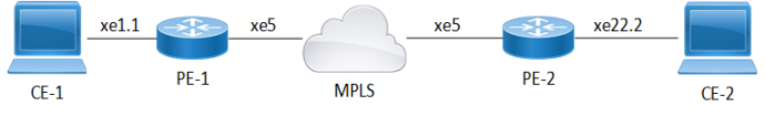
The topology consists of two Customer Edge devices (CE1 and CE2) connected to Provider Edge devices (PE1 and PE2) through sub-interfaces. The Provider Edge devices are interconnected through MPLS. In this topology, the Link Loss Forwarding (LLF) configuration for an EVPN Ethernet Private Line (EPL) service ensures fault propagation to prevent traffic blackholing during link failures. When a link failure occurs, such as between CE-1 and PE-1 on interface xe1.1, PE-1 detects the issue and withdraws the Ethernet Auto-Discovery (AD) per EVI (RT-1) route. This withdrawal is propagated through the MPLS network to PE-2, which then takes action to bring down the corresponding physical interface (xe22.2). This mechanism ensures the fault is communicated end-to-end, allowing CE-2 to detect the failure and trigger failover mechanisms. LLF is enabled through the LLF enable command at the interface level, ensuring automated fault detection and seamless service continuity.
Figure 38. Link-loss Forwarding Topology