MPLS Layer-3 VPN Configurations
This chapter contains configurations for MPLS Layer-3 Virtual Private Networks (VPNs).
Overview
The MPLS Layer-3 VPN solution provides address space and routing separation via the use of per-VPN Routing and Forwarding tables (VRFs), and MPLS switching in the core and at the edge of the network. VPN customer routing data is imported into the VRFs utilizing the Route Target BGP extended community. This routing data is identified by a Route Distinguisher (RD) and is distributed among Provider Edge (PE) routers using Multi-Protocol BGP extensions.
Terminology
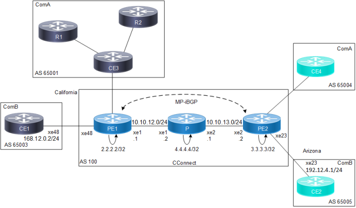
The following illustrates a Virtual Private Network in a CConnect Service Provider Network. This illustration corresponds to the terms defined in this subsection.
Figure 22. CConnect Provider with ComA and ComB Customers
| • | Service Provider |
The organization that owns the infrastructure that provides leased lines to customers, offering them a Virtual Private Network Service. In the above illustration, CConnect is the service provider providing services to clients ComA and ComB.
| • | Customer Edge (CE) Router |
A router at a customer’s site that connects to the Service Provider via one or more Provider Edge routers. In the above illustration, CE1, CE2, CE3 and CE4 are all CE routers connected directly to the CConnect network.
| • | Provider Edge (PE) Router |
A provider’s router connected to a CE router through a leased line or dial-up connection. In the above illustration, PE1 and PE2 are the PE routers, because they link the CConnect service provider to its clients.
| • | Provider Core Router (P) |
The devices in the core of the service provider network, which are generally not Provider Edge routers. In the above illustration, the P router is the Provider device, not connected to any customer, and is the core of the CConnect network.
| • | Site |
A contiguous part of the customer network. A site connects to the provider network through transmission lines, using a CE and PE router. In the above illustration, R1, R2 and CE3 comprise a Customer network, and are seen as a single site by the CConnect network.
| • | Customer Router |
In the illustration above, R1 and R2 are the Customer routers, and are not directly connected to the CConnect network.
VPN Routing Process
The OcNOS MPLS-VPN Routing process follows these steps:
| 1. | Service Providers provide VPN services from PE routers that communicate directly with CE routers via an Ethernet Link. |
| 4. | A unique Router ID (usually the loopback address) is used to allocate a label, and enable VPN packet forwarding across the backbone. |
| 5. | Based on routing information stored in the VRF table, packets are forwarded to their destination using MPLS. Each PE router allocates a unique label to every route in each VRF (even if they have the same next hop), and propagates these labels, together with 12-byte VPN-IPv4 addresses, through Multi-Protocol BGP. |
| 8. | The egress PE router pops the BGP-specific label, performs a single label lookup in the outbound interface, and sends the packet to the appropriate CE router. |