Configuration for RSVP Auto Bypass
This section shows the configuration of the various nodes within the topology to set up a RSVP-Auto bypass tunnels.
Topology
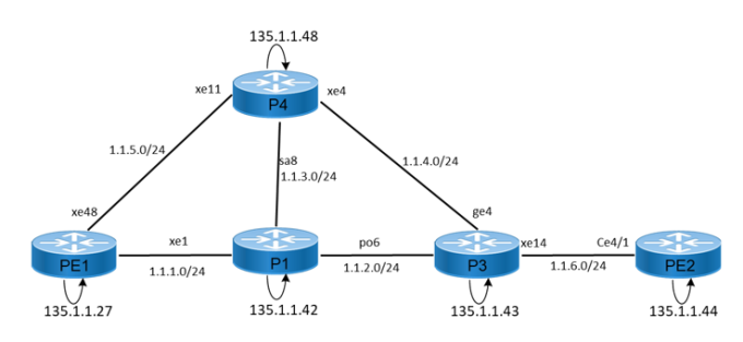
The sample topology includes Edge Nodes (PE1 and PE2) and core Nodes (P1, P3, and P4). As per sample configurations, Primary path is defined via PE1-P1-P3-PE2 using strict hops and auto bypass tunnel creation is formed on PE1.
Figure 99. RSVP-Auto Bypass Configuration
Before configuring RSVP-Auto bypass tunnles, meet all Prerequisites for the following nodes:
| • | Edge nodes: PE1 and PE2 |
| • | Core nodes: P1, P3, and P4 |
Auto bypass feature helps in automatically forming bypass tunnels and protecting the facility backup protection requested tunnels.