Configuration
Configure various nodes within the topology to set up an MPLS EVPN E-Tree Scenario 1 network, ensuring EVPN E-Tree for All-Active and Active-Standby redundancy and load balancing.
Topology
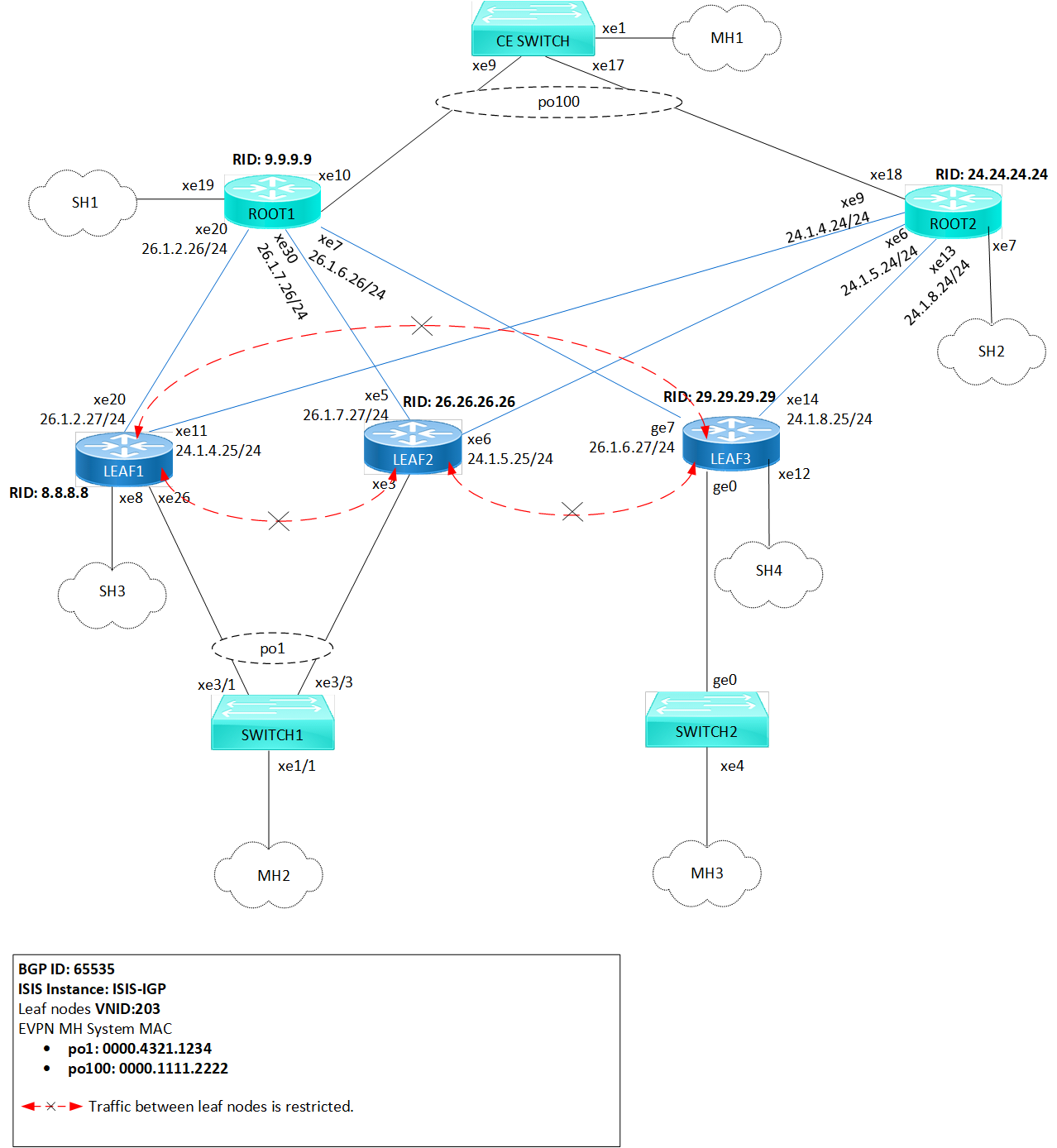
In the sample topology, Leaf nodes (LEAF1, LEAF2, LEAF3, and LEAF4), Root nodes (ROOT1 and ROOT2), and Switches (CE SWITCH, SWITCH1, and SWITCH2) form the network architecture. LEAF1 and LEAF2 are part of a Multi-homed group, with both connected to po1 (MH2). LEAF1 and LEAF3 have single home access-if ports (SH3 and SH4, respectively). Similarly, ROOT1 and ROOT2 are part of a Multi-homed group with po100 (MH1), and they each have a single home access-if port (SH1 and SH2, respectively). Leaf nodes are interconnected, and CE SWITCH, SWITCH1, and SWITCH2 are configured for Multi-homed connections to Leaf and Root nodes. SWITCH1 connects to LEAF1 and LEAF2, while CE SWITCH links to ROOT1 and ROOT2.
Figure 62. MPLS EVPN E-Tree Topology
Before configuring E-Tree SC-1, meet all Prerequisites for the following nodes:
| • | Leaf nodes: LEAF1, LEAF2, and LEAF3 |
| • | Root nodes: ROOT1 and ROOT2 |
| • | Switches: CE SWITCH, SWITCH1 and SWITCH2 |
Enable EVPN E-Tree
The following E-Tree SC-1 configurations applies to Leaf and Root nodes within the MPLS network.
| 1. | Enable EVPN E-Tree SC-1 which allows the nodes to participate in E-Tree functionality within the network, controlling traffic and establishing hierarchical connections between Leaf nodes in the network architecture. |
(config)#evpn etree enable| 2. | Set the MAC ageing time (60 seconds) to allow MAC addresses learned over EVPN MPLS to remain in the MAC table before timing out. Configure the global VTEP IP address (8.8.8.8) which serves as the global identifier for MPLS encapsulation and decapsulation within the network, facilitating proper communication and tunnel establishment. |
(config)#evpn mpls mac-ageing-time 60
(config)#evpn mpls vtep-ip-global 8.8.8.8
| 3. | Define MPLS identifier (203) to support hierarchical connectivity and traffic control within the EVPN MPLS network. On the EVPN MPLS node, specify EVPN-BGP as the host reachability protocol for the specified VRF (vrf103) to communicate and exchange reachability information within the network. To enable EVPN E-Tree SC-1 on Leaf nodes, configure etree-leaf along with the MPLS identifier. This allows for efficient replication of traffic at the ingress point, optimizing the functionality of E-Tree Leaf nodes within the network architecture. |
(config)#evpn mpls id 203 etree-leaf
(config-evpn-mpls)#host-reachability-protocol evpn-bgp vrf103
(config-evpn-mpls)#exit
| 4. | Enable port-VLAN mapping (po1) with VLAN ID (103) to facilitate multi-homed access. Enable EVPN functionality on the interface, allowing it to participate in MAC address distribution across the network. |
(config)#interface po1.103 switchport
(config-if)#encapsulation dot1q 103
(config-if)#load-interval 30
(config-access-if)#access-if-evpn
(config-access-if)#exit
Validation
Use the show commands described in this section to verify the network for proper MPLS EVPN E-Tree SC-1 configuration.
Verify LDP sessions on all leaf and root nodes by using the show ldp session command. The state field (OPERATIONAL) indicates that the LDP session between the device and its peers is currently active.
LEAF1#show ldp session
Codes: m - MD5 password is not set/unset.
       g - GR configuration not set/unset.
       t - TCP MSS not set/unset.
       Session has to be cleared manually

Code  Peer IP Address      IF Name    My Role    State      KeepAlive  UpTime
       24.24.24.24        xe11       Passive   OPERATIONAL   30    01:13:29
       9.9.9.9            xe20       Passive   OPERATIONAL   30    01:13:29
Verify RSVP sessions on all leaf and root nodes by using the show rsvp session command. The State field (UP) indicates that the RSVP session between the ingress and egress routers is active and operational. Identify the different paths established within the network using the LSPName field.
LEAF1#show rsvp session
Type  : PRI - Primary, SEC - Secondary, DTR - Detour, BPS - Bypass
State : UP - Up, DN - Down, BU - Backup in Use, SU - Secondary in Use, FS - Forced to Secondary
* indicates the session is active with local repair at one or more nodes
(P) indicates the secondary-priority session is acting as primary

Ingress RSVP:
To              From            Tun-ID   LSP-ID   Type   LSPName                         State Uptime    Rt  Style  Labelin  Labelout
9.9.9.9         8.8.8.8         5001     2201     PRI    LEAF1-ROOT1-Primary             UP    01:13:16  1 1 SE     -        25601
24.24.24.24     8.8.8.8         5002     2202     PRI    LEAF1-ROOT2-Primary             UP    01:13:05  1 1 SE     -        25601
Total 2 displayed, Up 2, Down 0.

Egress RSVP:
To              From            Tun-ID   LSP-ID   Type   LSPName                         State Uptime    Rt  Style  Labelin  Labelout
8.8.8.8         9.9.9.9         5001     2201     PRI    ROOT1-LEAF1-Primary             UP    01:13:45  1 1 SE     25600    -
8.8.8.8         24.24.24.24     5001     2201     PRI    ROOT2-LEAF1-Primary             UP    01:13:24  1 1 SE     25601    -
Total 2 displayed, Up 2, Down 0.
Verify the BGP session status on all leaf and root nodes, using the show bgp l2vpn evpn summary command output. The Up/Down field indicates the duration for which the BGP session has been up or down.
LEAF1#show bgp l2vpn evpn summary
BGP router identifier 8.8.8.8, local AS number 65535
BGP table version is 33
1 BGP AS-PATH entries
0 BGP community entries

Neighbor      V AS     MsgRcv  MsgSen  TblVer  InQ   OutQ   Up/Down  State/PfxRcd     AD  MACIP  MCAST    ESI  PREFIX-ROUTE
9.9.9.9       4 65535  514    443      33      0     0      01:13:53           114     59     5     50      0         0
24.24.24.24   4 65535  504    443      33      0     0      01:13:54           109     59     0     50      0         0
26.26.26.26   4 65535  322    391      33      0     0      01:13:23            49      0     0     49      0         0
29.29.29.29   4 65535  197    392      33      0     0      01:13:54             6      0     0      6      0         0

Total number of neighbors 4

Total number of Established sessions 4
Verify ESI information and the forwarding tunnel status on all leaf and root nodes, by examining the show evpn mpls command output. The DF- Status field displays the forwarding status as either a Designated Forwarder (DF) or Non-Designated Forwarder (Non-DF), and the ESI field displays the Ethernet Segment Identifier associated with each entry.
LEAF1#show evpn mpls
EVPN-MPLS Information
=================
   Codes: NW - Network Port
          AC - Access Port
         (u) - Untagged

VPN-ID   EVI-Name     EVI-Type Type Interface ESI                           VLAN      DF-Status Src-Addr         Dst-Addr
___________________________________________________________________________________________________________________________
203      ----         L2       NW   ----      ----                          ----      ----      8.8.8.8          29.29.29.29
203      ----         L2       NW   ----      ----                          ----      ----      8.8.8.8          9.9.9.9
203      ----         L2       NW   ----      ----                          ----      ----      8.8.8.8          24.24.24.24
203      ----         L2       NW   ----      ----                          ----      ----      8.8.8.8          26.26.26.26
203      ----         --       AC   po1.103   00:00:00:43:21:12:34:00:00:00 ----      DF        ----             ----
203      ----         --       AC   po2.103   00:00:00:33:33:44:44:00:00:00 ----      DF        ----             ----

Total number of entries are 252